When working with DMX and all that goes with it, there's a couple of things that will add upp quick. First: good DMX controllers are not cheap! Neither is any decent
sort of PC software/hardware. Second: cables! You need tunz of them, for the DMX signal and power for each piece of equipment you want to run. Last, the dmx devices themselves are not cheap either.
Yes, you can get a DMX LED device for next to nothing from your friendly chinese shop, but the quality of those is debateable.. Decent ones run up the bill quite fast.
Sometimes though, the speed DMX runs at is not needed, and it's good enough to change something on a device every once in a few seconds, or even just set it and leave it alone. Also, it would be great if
you could just cut the cable and attach a device somewhere in the middle without having to do a whole lot soldering, running new cables and power.
For this purpose, i came up with this 2-wire system that provides exactly that.
MDC is just a made up name since it can't be called DMX. It has no industry standard of any kind, it is merely created for places where there is no need for high-end systems that run 24/7 at high speed
but simply need a simple setup which usually is temporary (an evening for instance). So it's probably no good for a DJ party but will do quite nicely for shows or lighting
where things do not have to update on-que, at a fast rate or lots of thing happening at the same time.
MDC is mainly comprised of combining several existing ideas in one 'package'. All it needs is 2 wires running along every point that has a device and nothing else. Both power and data is received through the same 2 wires.
The basic principle to accomplish this is described in the train model digital control called: DCC, normalized by NMRA: https://www.nmra.org/dcc-working-group
What this boils down to: a frequency controlled square wave. The client taps into this signal by directly 'reading' the square wave signal for data and get power from that same signal by sending the square wave
through a rectifier and some sort of power cirquit that provides both power for the logic (usually 5V) and whatever the device is controlling (led's, motor, etc).
The protocol and data that is transmitted with DCC is ment for trains and switches.. not for lighting. So this is not used and replaced with a much simpler scheme, although some of it is borrowed.
The MDC data is alike DMX data, in that it sends data for a channel as one byte, giving it a value range of 0 to 255. The big difference is that, contrary to DMX, only changes are sent if there are any.
This change does mean that the protocol has to first tell the devices attached what channel changed, and what that change is.
So the simplified data 'package' is the channel number followed by the value.
Since both do not exceed 255, both are just one byte.
DMX has 512 channels, but it is not practical to have 512 devices on one cable pulling power from one power supply. So the number of channels is limitted, one byte can handle 255 channels,
which also is more than any sensible power drain.
Whatever is used to translate DMX to MDC signals will have to take care to receive and send out the correct channel numbers (which the DMX to MDC bridge detailed here does).
You could think of this system as the old DC powered lights that you can just cut the wire, splice in a new light, connect the stuff together and it just works.
The only difference is, that with MDC you can control what that light does (dim, color rgb, flash) and do more even like attach a devices like a movinghead controlling steppers etc. etc..
Also worth noting: unlike DC power, here it doesn't matter how you connect the 2 wires, the devices will adjust to any switch in 'polarity'.
All devices have some common 'traits' nomatter what it does if using the standard libraries:
- There is no 'in' and 'out', only an 'in'. All devices are attached to the same 2-wire "bus", the device does not have to repeat the signal and pass it on.
- The code is small enough to run on an ATTINY45 (at least, all devices presented here fit).
- The device will detect wrong "polarity" of the signal and will adjust to it.
- Programming the channel is done using one button and the controller itself. By pressing and holding that button for 3 seconds, the device will switch to 'program mode'.
Changing one channel at least 10 times will set the channel.
- The set channel is saved in EEPROM and will be used after every (re)start.
- All subsequent channels the device might use are relative to the first channel.
- The 'bus voltage' is set to 12V. A higher voltage can be used, but that would mean checking if the 7805 power regulators used do not overheat and
the resistor used for limitting current of the opto-coupler is still enough so no magic smoke appears. For the devices outlined here anything from 10 to 13V shouldn't be a problem.
- Depending on the function, it can use all the current the power supply and the used MDC controller can deliver, there really is no set maximum on this.
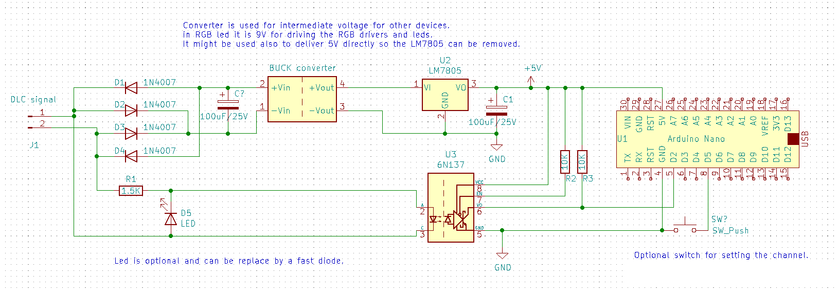
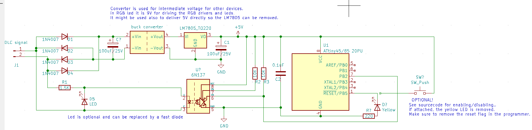
Below are the circuits for a basic client using an arduino nano or an attiny45/85. The code is made to actually fit in the 4KB space of the attiny45! Use these circuits as a startpoint for building an MDC client.
The code usually is not that hard to make, it also can be pretty standard. For examples of this see the projects described here.

 The button is used to set the MDC channel by holding it 3 seconds and then change the value of a channel at least 10 times. On a DMX controller, it's enough to move the channel slide up all the way and then down, do this not too quickly and the channel will be set.
To make it easy to build devices, a couple of libraries are available. Not much more code is needed to actually make a device work. Ofcourse the code to actually make it do what it is supposed to is
needed, but usually that's not much.
The current state of the libraries is that they do detect the type of atmel chip that is used (or: the arduino that is used).
If it can't use the atmel chip or arduino, it will throw an error when trying to compile it.
All library files. Store these in the library folder of the arduino GUI
For everybody that wants to dive into the theory how things work, you can read it on the theory page for MDC