For everybody wanting to use this idea and extend on it, or change the whole thing alltogether to suit your needs, here is the complete dry theory on how things work.
I will try and touch all aspects and make it as clear as possible.
In a nuttshell: the power is delivered using something similar to AC power: a square wave that alternates positive and negative, like in the picture below:
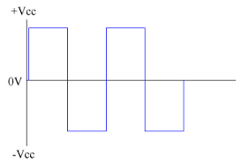
Because of this, getting power from this is the same as when AC power is applied: first feed it to a full bridge rectifier, add a capacitor to eliminate any ripple, peaks or valeys, and then add a power regulator like a 7805.
The amount of current is really only limited by the power supply of the whole system, the current draw of other clients and the maximum current the H-bridge in the master controller or bridge can handle.
Vcc is asumed to be 12V in all MDC devices on this website, but this can be adjusted to your need.
Keep in mind: there is a powerdrop introduced in several places. For instance, the L298N module has a powerdrop of around 2V. Then there is usually 0.7V lost on the bridge rectifier, and in some cases even the
cable length plays a part.. Worst case, with 10M of thin cable it is possible for the power to drop as low as 7 or 8V!! So keep this in mind when setting things up or making changes!
The data to the clients is carried to the clients using the same square wave that delivers power. There is nothing strange going on like adding some sort of waveform ontop of this square wave, just the square wave
is used.
Instead of using alsort of complicated modulation, this system simply makes the square wave wider or narrower in time, creating a simple form of frequency modulation.
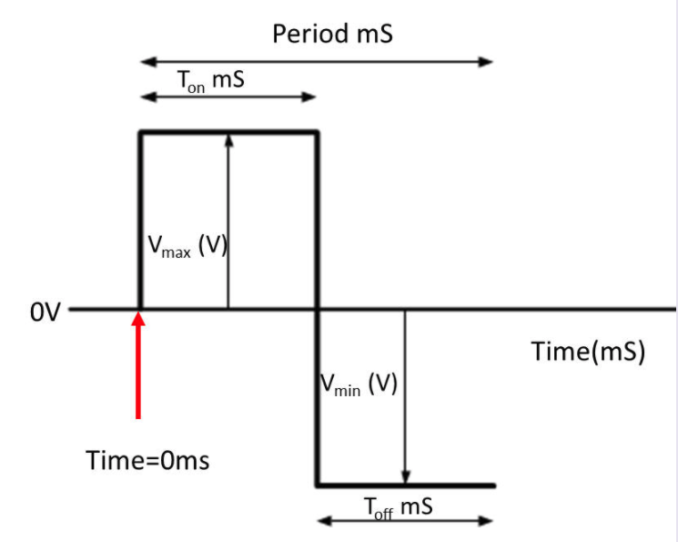
Using the image above, the square wave is symetrical when: Ton = Toff and Vmax = -Vmin = 12V. The square wave must be symetrical to keep things simple in detection of data and polarity of the signal.
To send the bitstream, only the Period is altered.
In the MDC system, only 3 different Period times are defined: 0.1mS = '1', 0.14mS = '0', 0.18mS = 'space'.
All the devices described on these pages will asume these values.
To pull data from the 2 wires, all that needs to be done is connect to the raw signal before the bridge rectifier, and detecting the rising or falling edge of the signal, not both. This will provide for enough time
on the client to handle the decoding etc.
To be able to detect if something is a 1, 0 or space, it's a simple matter of measuring the time between the current time and the last edge, and compare that to the known Periods.
The 'polarity' of the signal can be easily detected by keeping an eye on the Periods. If the time clearly lands in the middle of the known Periods this means the polarity is wrong.
The reason for this: if we start out detecting the rising edge of the square wave, and a 1 is sent, then we should see a period time of 0.1mS.
If the polarity is wrong, and the signal is all 1's, then nothing strange can be noticed. But usually, there are 0's and 1's in a byte, which is when things start to go sideways.
Suppose, a 1 is sent first, and the polarity is wrong. Then the square wave will start with a falling edge followed by a trigger at the rising edge at 0.05ms.
We then get a falling edge at Toff when the next bit starts. If that happens to be a 0, then the next trigger at a rising edge will happen around 0.07mS.
The measured time between the 2 rising edges becomes 0.12mS, which is neither a 1 or a 0!
If the interrupt trigger is flipped to use the falling edge of the signal, then things are correct again.
In the library for MDC, this method of detection is however not employed because even 0.1mS is just too short when an ATTINY is used to do all the comparing etc.
Instead, another way of detecting is used, be it that it might be a bit less solid.
The trick employed for this: the hamming decoding. We simply say: if we get 10 repeat errors right after another, we can somewhat safely say: probaly, the data is read wrong, so lets flip the edge detection and see if that helps it.
So far with all tests, it turns out this method does seems to work surprisingly well.
An example of a simple circuit to pull the data and be able to detect a rising or falling edge is shown in the picture:
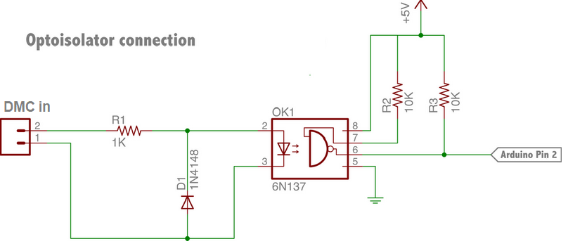
The 1n4148 diode can be replaced by a LED. It will not show if the signal on the wire is correct, but just shows: there's something there that has a voltage.
Pin 2 of the arduino is used since on most atmel avr's, pin 2 can be connected to the INT0 interrupt on a rising, falling or both edge.
The protocol used in MDC is a simple one. All data is transferred in frames:
- a '1' bit to notify everybody something is coming
- a 'space' to give all devices time to set things up and wait for the data
- 2 mode bits
- 32 data bits
- a 'space' to give all devices time to handle and store the information
The last space is added to provide a little bit of extra time for slow cpu's, they can handle the copying of data to a buffer of some sort in that time and reset it's registers to get ready for the next frame.
All frames are repeated at least twice, to make sure the target client 'sees' the frame.
The mode bits are for future use, they are always 0 in the current code. The datastream is the part that has the data for the clients.
Also note that unlike DMX, only updates are sent when something has to change, otherwise only all 0 data is sent to keep the DMC signal alive.
Only sending changes frees up bandwidth and enables the use of a slower bitrate than the 250kbaud DMX uses so cheaper cpu's can be employed.
All data is sent using hamming (8,4) encoding to provide error detection and correction.
This usually involves calculation etc, but this is actually not needed! The whole encoding/decoding has been turned into a simple lookup array that either shows the correct value or an error. The table is set up so that a 1 bit error will be corrected.
For the purpose of hamming encoding and decoding a .h file is in the library. It has a result for each possible bytevalue, but it does take up 256 bytes of program memory. It does however warant the memory because it does
increase the speed of decoding considerably.
All data consists of 2 bytes hamming encoded data for the channel number and the same amount and encoding for the value for the channel.
Once decoded, we're left with 1 byte for the channel number and one byte for channel data.
As stated elsewhere, this is half the channels of DMX, but more are not really needed when considering the power drawn by 255 clients. At that point, it's better to employ a second bridge with it's DMX channel
starting at the last channel + 1 of the previous one.
On the DMC 'bus', channels counting is independent of the DMX channel numbers and never changes. The DMX channel numbers are always transferred into the correct DMC channel.
This means that whenever the DMX channel changes, no change is needed on the DMC 'bus'! This way, it is possible to pre-set all devices, and hook it up in any DMX universe starting at a free DMX channel.
The channel value is always a 1:1 copy of the DMX data.
Note that most of this is based on the DMX to MDC bridge, but will apply in general.
At the base of things to create the square wave will in most cases be a H-bridge. There are different ways to make one. For the lower currents there are plenty of modules available, but to always check the
voltage drop of those. For instance, the L298N has a voltage drop of 2V!
For higher currents, there are less choices, and in some cases even building one yourself using mosfets is the only way.
Using a H-bridge really is no different than driving a motor either clockwise or anti-clockwise, just that in this usecase this reversal changes all the time and much faster.
Because of the use case, it does matter however that the timing is precise, else clients will not be able to decode things.
In the implementation in the DMX to MDC bridge, this is accomplished by using the PWM option with a twist of the atmega328, because we do need 2 PWM signals which are exactly the opposite of eachother.
To accomplish what we want, we use the so-called phase correct-PWM of the atmega. In this mode, the PWM timer is simply set up to count up and down with 2 values it compares the current counter to.
Drawn on a graph, this can be seen as a sawtooth signal as is displayed below.
We could actually use OCnA and OCnB to generate our wave, but we don't want the counter to directly control the PWM signal, since we want to do other stuff whenever that counter hits 0.
On the graphic, one item is missing that is important to create the correct wave timings: the ICRn register. This controls the maximum that the PWM counter will count to. In the image, this is a hard value of 255, but using the register we can change this value
The trick now is to set up this counter just right.
Since timer0 in arduino's (and most atmel avr's) is used to make millis() and micros() function, the code doesn't touch this timer.
Instead, timer1 is used, controlled by TCCR1A, TCCR1B, OCR1A OCR1B and ICR1.
Of these values, we only use the TCC registers to set things up, OCR1A to set the value high or low for pin9 and ICR1 to set the period of the wave.
We do set up pin 9 as PWM pin, so the cpu knows what is expected by TCCR1A = _BV(COM1A0) | _BV(COM1A1).
Next, we set the prescaler to 8 and we set the mode of the timer: TCCR1B = _BV(WGM13) | _BV(CS11).
This results in a nice setup to use, since we actually don't have do do much calculating for setting the period!
It just so happens, with the atmega running at 16Mhz, if we set up the prescaler to 8, then the we can just set the maximum of the counter to half the period.
Since ICR1 defines the maximum for this counter, we can simply set it to half the time of the 'bit' (0,1 or space) we want to transmit and we're done.
Keep in mind that this interrupt is actually called twice per period!! once at the 'top' and once at the 'bottom', so we do not have much time to do any work like encoding.
If the timer is then connected to an interrupt that sets the output ports to the correct value as it's first order of business, we have a correct, timely swap of the signal.
Next is checking state and what bit is to be sent out, and advance to the next frame once the current one is finished.
The interrupt routine expects an array with data that contains the mode bits and the bitstream already hamming encoded. Each buffer has a counter set up, which determines the number of times this frame has to be repeated.
Sending bits becomes easy by simply shifting out the mode bits and then the bistream.
Every interrupt, we can just flip any port from high to low and vise-versa. In the code, ports 11 and 12 are used, making it possible to set both ports in 1 write operation, so there is no chance of
the H-bridge shorting out because of delays in setting each port.
If desired, a 'dead time' could be introduced, which means holding both pins low for a couple of nanoseconds, and only then write the correct value. This does introduce some time that there is no power on the line at all so a bigger capacitor is needed on the
client side to make sure there are no resets because of a low power situation.
In the current code this is not implemented because the change does happen in the same write operation. If this fails, there's probably bigger issues than the signal to the H-bridge.
It is also possible to actually use one port and branch off the signal through an inverter that can then set the other side of the H-bridge. The problem is that this does incur a slight delay because of the inverter
which in turn means that the signals do not flip at the exact same time. Although this might be in the nanosecond range, with high currents this is noticable by the mosfets heating up more.