This RGB led light uses up to 5 channels, and can be built even using an ATTINY45!
The idea revolves entirely around the fact that any arduino (including the ATTINY series) can handle PWM on multiple channels at the same time, provided things are coded correct.
One added 'issue' is that timer0 cannot be reprogrammed because then the client code will not work: it needs correct millis and micros.
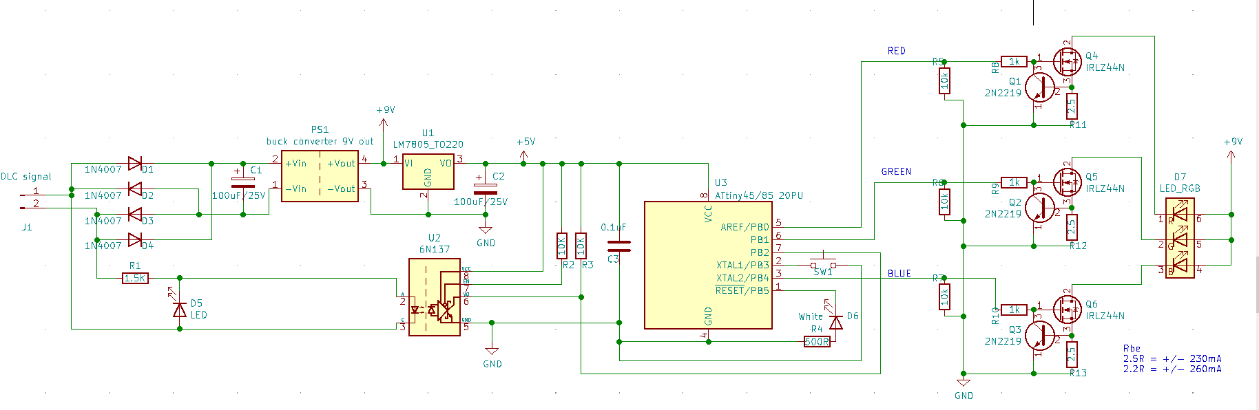
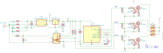
Even so, it is possible to implement an RGB light. With an 8 pin ATTINY, this is the extent of the possibilities (using the remainder of the pins for signalling and the channel learn button).
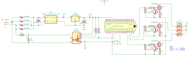
If instead using a nano and larger ATTINY chips, it is possible to add things like a WHITE or UV channel.
The code and hardware is set up initially to deal with just RGB.
This circuit implements a basic RGB light which has 5 channels, laid out as:
- 0 - Red
- 1 - Green
- 2 - Blue
- 3 - global dimmer
- 4 - strobe, 0 - 50 = no strobe, above this: the higher the value, the faster the strobe flashes.
0 is ofcourse the base channel that is set for this light fixture.
The strobe will not just flash everything 100% but will respect the settings of the other channels, so it is possible to strobed in a set color as bright as is set.
The hardware is set up to use 2 different voltages coming from the 12V signal coming in: 9V for the LED(s) and 5V for the logic.
The 9V is created by using a buck converter, that can drive the needed current for the LED. Since the RGB LED used is a 1W led, with 300mA per channel, this means that the buck converter will have to be at least a 1A type (considering there is no 900mA converter).
It's good to use a 1.5A version, which will then be able to first provide power for the LED, and also employ a 7805 regulator for the logic.
The LED is driven using a basic constant current circuit, one for each channel, using a mosfet and a transistor, which both are fast enough to do PWM coming from the arduino.
The given values for the resistor connecting the drain of the mosfet to ground is actually a bit higher than it can be. The reason for this: the loss in light power is hardly noticable, but the heat produced
when driving the LED at less than full power is considerable. If you can cool things with a bigger fan and cooler, than you could lower the resistor.
I designed 2 circuits for lights, so it is possible to cram this into even a very small PAR16 spotlight! (see the bottom of the page on this, i do have 3d printed stuff for this!).
The top circuit is built by starting with the generic circuit and expanding it to drive the LED's. The bottom one is a redesign using an attiny45 (or 85).
Click on the images to get a larger picture.
I would advice against building a fixture with for instance 12 x 1W. This circuit is simply not ment for this and usually it is better to use a higher voltage for driving the LEDS, which then are
connected in series. This will then keep the current to an acceptable level, but can't be driven directly from the MDC signal.
It is possible ofcourse to use a higher voltage for the MDC signal instead of 12V, but i would advice against running something like 60V over the 2 (usually cheap) wires.
Instead it will be better to attach a seperate powersupply for just driving the leds. It does negate the advantage of 'just 2 wires', but does allow the system to drive large current devices.
The code is split for 2 purposes: ATTINY45/85 and everything arduino (nano, micro, etc).
When using an arduino nano etc, then you can actually keep the USB connected that is used to program the arduino, and monitor the debugging information on the serial monitor.
The code for the attiny is different in that a bare bone attiny has nothing other than the chip, which has to be programmed using either an arduino or dedicated programmer.
There are several methods easily found on internet how to do this.
All code is downloadable as usual:
Not that when using the attiny circuit, you will have to add the correct "board" in the arduino GUI.
To add a working ATTINY compiler:
- in the GUI open 'file' and select 'preferences'.
- in the preferences screen, set a check next to the option: Show verbose output during: compilation.
- in the preferences screen, click the icon next to the 'additional boards manager URLs'
- add the url: https://raw.githubusercontent.com/damellis/attiny/ide-1.6.x-boards-manager/package_damellis_attiny_index.json
- click ok buttons until you are back in the main gui.
- Now, open up 'tools' and then 'boards'. You will see 'boards manager' in that menu, select it.
- In that list, look for 'attiny' by David a. Mellis and install it.
With that done, you will notice a change in the board manager menu. Select 'attiny controllers' and select the correct attiny.
Now, to get the hex file, load the code and only to a compile, not an upload.
Watch the debug screen, it will tell you where it saved the HEX file.
To use it, open up your preferred programmer software, and then load that hex file. When programming the attiny, make sure that:
- clear the eeprom, just to make sure
- make sure only the fused SUT0, CKSEL1, CKSEL2, CKSEL3, RSTDISBL are set, the rest not.
- make sure the code fits in the memory of the attiny.
The code 'as is' for the attiny will be using 3680 bytes program memory and around 117 bytes of dynamic memory. It also uses 1 eeprom byte for storing the current MDC channel.
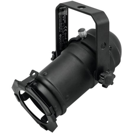
As stated above, i did create PAR16 lights using the attiny circuit. It's tight, but it does fit!
the type used: Eurolite PAR16 spot MR16 black, and they look like this:
If you buy them with a LED light in it, there's a piece of metal holding it in the center, which we will be reusing.
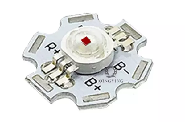
The LED used is a 1W rgb led on an aluminium backing plate, making soldering etc. much easier. They can be ordered premade like this, but the parts are also sold seperate if needed.
To be able to call it a spotlight, a lens will be necessary. These can be obtained in different types, but the ones used in this setup look like the image below.
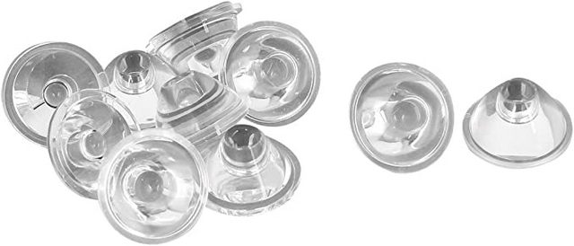
The nice thing is that you can buy them with different angles of view, so you can project a small spot or use it as a spotlight. To be able to change this, i created some 3d printable parts.
3d printable parts
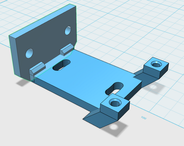
Below are the 3 parts to be printed for each par light. Starting with the back fixture, this has holes to fix it to the existing plate in the par light. The existing light fixture will have to be taken out for this..
The 2 stands with the holes in it, are for a 3x3x1 cm computer fan running at either 5 or 12V. It doesn't have to move a lot of air, just a little to blow out the heat created by the led and mosfets. You do have to tap some M3 threads in those holes, so the fan can be fixed with 2 M3x15 bolts.
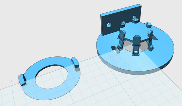
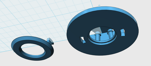
The top part is a bit more interesting. First, to be able to change the lenses a bajonet ring is made. The shown lens has a flange that fits in the edge made in the main part (bottom picture).
The lens can be put in, and the bajonet ring will lock it in place.
At the same time, the LED is put in like is shown (this part is not printed), it is held by the 6 stands so that it is always forced toward the front. Because of this, the lens will always have to push it back so it will sit tight against the led and keep it in place.
To build the circuit, a flat piece is added to the printable stl files. This is the 'footprint' for the PCB. It will have the holes in the correct place so it can be used as a template.
The PCB is sitting below the centerline of the PAR light, so it is possible to have the cooling for the mosfets to stick out a little bit.
A simple piece of experimental PCB can be cut to size for the purpose, and is used to connect the front and back pieces. Since there is no real mechanical force applied to things, this will work out fine.
Extra hardware needed to build it:
- 1 3x3x1cm fan 5 or 12 volt
- 4 M3x10 bolts
- 2 M3x15 bolts
- 4 M3 nut
- M3 thread tap
Coming soon
pictures of my built as an example and the images how i laid out the circuit on a PCB!!