For a general explanation of what MDC is, see the main page MDC
The 'device' described here is used to translate DMX data to MDC data so that the system can be integrated in a DMX setup, and the nice DMX controllers and software can be used.
Ofcourse, it is always possible to make a dedicated controller, or program things using a pi or something, but DMX is an existing 'universe' that can be used.
In a nuttshell, this bridge is connected to DMX and will output a correct MDC signal based on the DMX input signal.
The bridge cannot relay all 512 channels, because the MDC protocol only allows for a maximum of 255 channels.
Actually, this bridge limits the channels even more, because it is of no use to hold a big buffer of channels when there are for instance no more than 10 lights on the bus, taking at most 50 channels.
The number of actual channels can be set in the code and is adviseable to do so.
If there is data, the bridge will take care of hamming encoding and sending out the signal on the bus in the correct order.
If there is no data, a simple 'null' package is sent. Since channel 0 means nothing, this can just be ignored by all clients.
The code in the bridge does also a translation, so the channels on the bus will always start at 1, so the DMX channels are NOT repeated!
Instead, the MDC channels are always relative to the set DMX start channel.
The big advantage is that once set up, a change in the DMX channel does not also mean the MDC devices have to be changed.
Last, the module reads the incoming DMX datastream and takes what it needs from that stream. It then determines what the changes are, and if there are any, output this to the MDC bus.
To set the main DMX channel, 2 methods are available: 1) set it in the code and never change it. 2) simply set channel 1 in the code, then use the button to change it.
Normally, a DMX device is set to a channel using a couple of buttons you have to push a lot of times for the higher channel numbers.
The code of this bridge has an easier method: make sure that all DMX channels read 0. Then, push the button on the bridge 3 seconds. It will switch to 'program mode'.
Now, just posh the desired channel to a value of 255, the bridge will detect this and set the channel.
It will save this to eeprom, so it will remember that setting.
The current DMX basechannel and maximum channel number is displayed on the oled, along with the availability of the DMX signal and wether or not the power is switched on for the MDC bus.
The basics of the hardware revolves around 3 modules: an arduino nano, a max458 module and a H-bridge like L298N, the 'bigger' BTS7960 double h-bridge module or another H-bridge that will drive
enough current and can keep up with the PWM signal for the MDC bus.
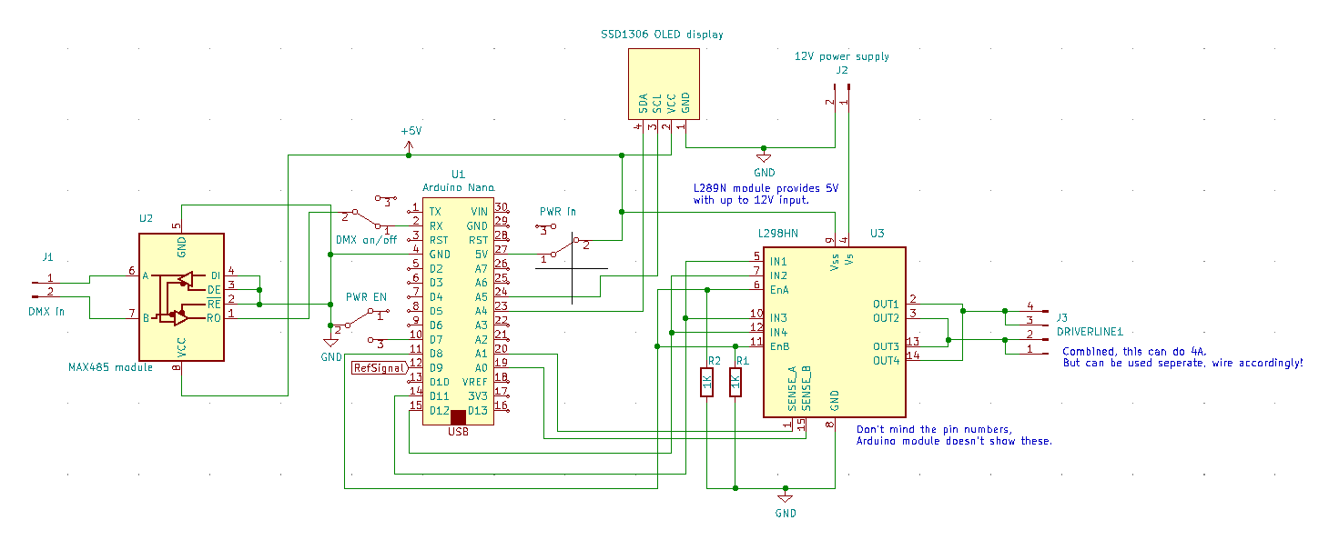
The schema for building a bridge (click to get a bigger image):
The max458 takes care of receiving the DMX signal and transforming this into a ttl level bitstream that is fed directly to the serial in port of the arduino. Usually this port is occupied by the
USB serial when using the arduino GUI, but that's not possible when runnind DMX. Not only is DMX running at a faster rate than what programming is done at, and the serial monitor only goes up to
115.2kbaud, while DMX runs at 250kbaud, with some of it not at all compatible with standard serial protocols.
For this reason it's necessary to have a jumper or switch in between the DMX signal coming from the max458 module and the serial in pin of the arduino. While this signal is connected programming the arduino
will result in failure.
Another jumper or switch is added for the same purpose: on the 5V line coming from the H-bridge in use. The used L289N module provides 5V via an onboard 7805 chip. It is never a good idea to have it connected when plugging
in the USB port, so whenever this happens, cut the connection to that power supply.
A third jumper or switch is added to cut the outgoing power of the H-bridge. This is controlled by the arduino, so it can be done by software, but it is sometimes nice to be able to control it manually.
To be able to show some settings and what is going on, a small SSD1306 oled can be added. The code provides for using this display in the least intrusive way possible so sending data to it wont interfere
with reception of DMX data or maintaining the MDC signal.
The bill of materials to build the basic bridge:
- One experiment PCB, the size depends on the model you are making. The smnall example below is 5x7cm
- Thin wire to make some of the connections
- headers, enough to to seat the arduino, max458 and oled modules.
- 3 2 pin male headers for jumpers
- 3 jumpers
- 1 pushbutton switch, normally open
- one power supply, output depends on the H-bridge used, considering the voltage drop
- one arduino nano
- one max458 module
- one H-bridge module (L298N or a double BTS7960 43A H-bridge module)
- optional: one oled SSD1306 display
- Optional, depending on the H-bridge module: a 7805 power regulator + a 100uF capacitor
You can add things like external switched instead of jumpers etc and some other electronics might have to be added to connect the chosen H-bridge.
Building the bridge mainly consists of placing all parts on a piece of experimental board, using risers to plug the modules in. This way, any module that might burn out can easy be replaced.
2 examples of possible layouts and size can be seen in the pictures below:
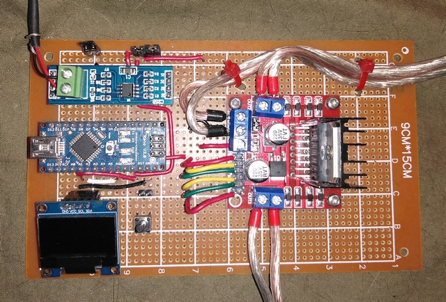
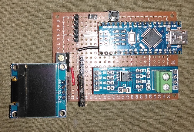
The button that is visible on the pictures is used to set the DMX channel.
Instead of fiddling with buttons up and down etc, this works the same as on any DMC client. Hold it for 3 seconds and the bridge will switch to learning mode. The first channel not showing a 0 will be taken as the new DMX base channel.
This will be shown on the display and will be stored in EEPROM.
The number of channels the bridge will occupy can't be changed and is set in the code when programming the arduino.
The code really can be thought of as 3 'sections' that take care of incoming DMX data, outgoing MDC data and a part that 'glues' everything together and does the supporting stuff.
The DMX is received constantly and stored in a buffer. Only the amount of channels configured is used so the buffer is just large enough for this.
Receiving DMX data is done using an interrupt routine connected to the serial port. As soon as this has a full byte or detects an error, then the routine is called. The interrupt routine does nothing much
than wait for the start channel to show up, then start storing the received data until either one happens: the last channel is received, a timeout happens (meaning no DMX signal) or we receive a start header
again denoting the start of DMX data.
All the DMX handling is put into a small library object to make it easy to update code or replace it with something entirely different.
The MDC signal is made using the theory described on the theory page. The data is set up in a buffer that has 'records' holding the mode bits, datastream and how many times that package
has been repeated. If 0, it's not repeated again.
All the parts for making it work is also put into a library for easy maintenance.
Last we have the 'glue' routines, for which the most important task is to detect changes in DMX channels, encoding the data and storing this in the output buffer of the MDC signals.
If enabled, it will also output the state of the bridge on a display, like the optional oled display. It will show the start and end DMX channel that is used, and the current state of the DMX signal (on or off) and the current state of the MDC power output (on or off).
Keep in mind when altering this setup that you use an arduino that at least is running at 16Mhz, any lower and either one of the interrupt routines will not finish in time and nothing will work.
Also keep this in mind when altering the code in the interrupt routine and check any new libraries you might add so they do not interfere with any interrupt or timing.
All the code and libraries needed to build the bridge (best to download by right-clicking on the links and use 'save as' in the menu):
Note: store the libraries in the arduino gui libraries folder before trying to compile and upload DMXbridge.ino to your arduino.