Back to home
Arduino laser shooting game This idea came into life when i was working on some promotional thing for scouting.
The idea was: wouldn't it be fun for the kids to have something to shoot with and to shoot at.
The first idea was to make some sort of ping pong ball canon, aimed at some cans. But that would mean i needed a vacuum cleaner.. and considering i wanted 3 of those, the idea was quickly abandoned.
As an alternative, i checked my parts drawers and came across enough stuff to make 3 laser guns with.
It kindof spiralled out of control from there.. ending up in a nice project!

So, after some drawing and designing, i came up with this idea:
We will have 3 guns, with a laser in it. It should have a limited amount of shots, and should be able to count the hits. For that, it has to have some sort of display.
It is also nice if some sort of sound is produced. It doesn't have to be hifi, some bleeps will do.
No wires will be attached to the guns, so nobody can accidentally damage a gun by breaking those. This means the gun has to operate on batteries.
Each gun will have it's own target, which should be able to move. Each gun will have it's own dedicated target, so no difficult encoding scheme is needed.
The guns should have a finite amount of shots, easily reloadable and the gun should be easy to clear for the next player.
Things to consider.. First of all, we are working with a laser. So some protection is needed for the eyes. The glasses for lasers depend on the light that is transmitted.
To make absolutely sure no accidents can happen, we will need those for the players and the person running the game.
Also, as an added security, the gun will not send out a steady beam of light, but will pulse the laser with each shot. Each pulse will be no more than 50ms, which is within safety limits of indirect exposure.
In NO WAY anybody should look straight into a laser, even if it's pulsed!
Last, when using the game, care should be taken that no reflection can come off the targets nor from anything surrounding the targets to anywhere.
So check if there are any reflective surfaces behind the targets!!
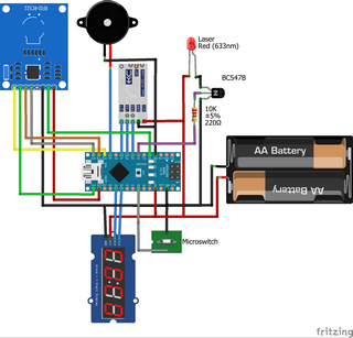
The gun The parts i pulled together for each gun:
The circuit i built:

(click on the image for a larger version)

The guns i got a hold of are simple things, small sized (kindof looking like colt M4) models that don't even have screws to hold them together.
The most important part is: it has to have space for all the parts in it (except batteries) and has to have some sort of working trigger mechanism. It doesnt matter what it does, as long as it can be used as a trigger.
The trigger mechanism is gutted so a microswitch can be installed, making the trigger press the switch while sliding past it, so the switch doesn't become the 'endstop' of the trigger.
It might be needed to alter the trigger itself a little, but this is entirely up to the creativity of yourself.
I liked keeping the trigger instead of just installing a switch because the gun looks like a gun still and a microswitch has less 'bounce'.

The batteries are in a seperate battery box, which i hotglued against the 'magazine', feeding the wires through a hole drilled straight through the housing and gun so no wires are exposed.
It sort of looks like one of those extra large magazines used with airsoft guns
Once done, the gun can be glued or tie-wrapped shut, so nobody can open it and tamper with the electronics (remember, there is a laser in it..).
I did remove any led's on the arduino and other electronics to save on power, so the gun should last at least a day on 3 AA batteries..

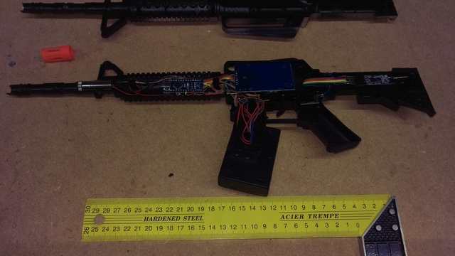
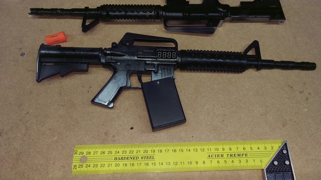
After all is done, here are the guns i made (the ruler is for reference on the size of them, click on the images to get a large view):


As you can see, the display is tucked away behind the trigger mechanism, the rfid reader is stuck ontop of it.
I used hotglue to stick everything in place so it won't move around or rattle when handling the guns.
The gun code The most important thing in the code would be the time sensitive pulse for the laser. It can in no way exceed the 50ms. So in the code, that is simply done by switching it on, waiting with a delay for 50ms and then switch it off again.
So it does interrupt everything else, but since it is only 50ms, it won't interfere to much. Besides, when a shot is fired, nothing else has to be done anyway.
Everything else, can be done 'in good time', since it is not time sensitive. Even the bleeps aren't because i used an active piezo.
These just need a plus and minus to beep so all that needs to be done is switch the port high, and switch the port low again in due time.

The rfid's are used to 'load' the gun and to reset it. For this, it's easiest to scan the rfid's, dump the id's to the serial and use the value.
Then assign each rfid to whatever function is needed.
In my case, i have 4 keychain models, and 3 cards.
The 4 keychain models, i assigned as such: Since the display can only handle a maximum of 99 shots, that's the maximum shots that the gun will accept when adding shots.

The cards i assigned as:
When the gun is cleared, all the functions switched on with a card are switched off.
All the card functions are switch on/off type, meaning: with each scan it will switch on and then off the corresponding function.

The hits are received from the controller module using the HC-12 modules. At first the gun will look for a ! sign, then followed by a gun number. If that is the number of this gun, then it will beep and add a hit.
For future purposes, it also scans for a + sign, followed by a byte denoting how many shots should be added. This could be used for remotely adding shots just like using the rfid's on the gun.

The entire code for the guns can be downloaded here: Lasergun code

When uploading to the guns, please note that each gun has its own number! This number is set in ascii code, so a 1 is actually 49. Find the line "#define GUNNUMBER" and change it to the correct value.
So: gun 1 = 49, gun 2 = 50, etc.
Targets A target is simple: it has to detect when a laser hits the right spot and then report that hit back to the gun and move to another posision (yes, i want them to move!)
The way i constructed the targets is to use a simple LDR with an arduino.
Since i don't want any wires to the gun, the hits are reported wireless to them using a HC-12 tranceiver unit.

And here comes trouble: when all targets have their own transmitter, collisions can occur. There are numerous ways around this with protocols, but i wanted to keep things simple...
Also, each unit has to get power somehow, preferably delivered from 1 source.
So instead of having a transmitter on each target, i made a central unit that will have the transmitter and supplies the power to each target.

For this, i went for UTP! Any UTP cable can handle power and signals (they do it with POE already in networks..).
The specs for what is allowed are more than enough for this project. Also, you can pick up UTP cables in various lengths, ready made, at any computer shop..

The UTP cable has 8 wires, which are used as: Combining 2 wires should be enough to handle the power of the servo, the arduino power is negligable compared to the servo.
The hit signal is simple: pulling it low signals a hit.

The targets are now simple setups using:
There are 2 jumpers in the circuit. The function for these:


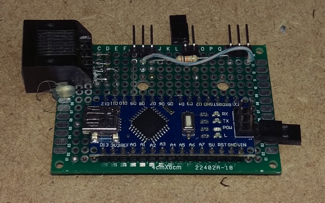
I put the arduino and RJ45 jack on a piece of experimental board (or hole board) adding some headers so the servo can be connected using the plug that is on it.
Also, i made the 'RUN jumper' and the 'TEST jumper' a 2 pin header with a jumper on it instead of a switch.

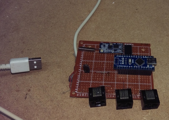
The central unit is made using: Each of the RJ45 has power connected as stated, but each of the jacks has wire 3 connected to a different port on the arduino.
This way, the arduino can tell what target has been hit, and can send the correct gun that signal.
So it makes no difference to the targets what gun they belong to, it is dictated by the port the UTP cable is plugged in to.

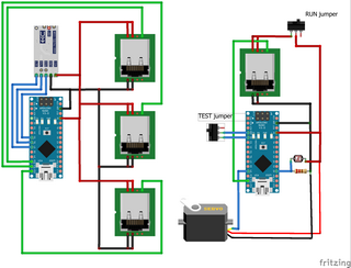
The entire schema for the central unit and the targets:

(click on the image for a larger version)
The target unit (on the right) gets it's power from the RJ45 plug, so no special power plug or leads are needed at the target.
The central unit can be powered by attaching a USB charger to the red (+5V) and black (GND) leads.


For the targets I put everything on a 60 X 40mm experimental board for easy installation on the target:


The controller unit i used a larger board (70 x 85mm) to put everything on so it's easy to add to:

For some extra fastening i hotglued the RJ45 ports to the board and added some extra on the sides.
Targets/central unit code The code for the targets themselves is pretty straightforward:

The cental unit code also is fairly simple:

Some things aren't used in my setup but is in the code for the controller:
I leave it up to you to do something with this. In this setup, it's all ignored, all targets are on all the time.

All the code can be downloaded here:
Since there are still 3 wires left, there is ample room for expansion, even employing i2c on it (by changing the wiring a little to each RJ45 jack).

In the code for the targets 2 extra ports are reserved: port 3 for signaling to the target to be active or not and port A1 for another LDR sensor.
If port 3 is high, the target will be inactive and will stop all function. If the line is pulled low, the target will be active.
The second sensor port is read, but nothing is done with that value, since no LDR is attached to it so far.

The code for the central unit has ports reserved for sending the active signal to the targets plus inputs for switches, but neither are used so far in the actual code.
Libraries needed The code uses a couple of libraries for the hardware used:
The mechanical construction Around here, you can get aluminium corner lengths of 1 meter at the local home improvement shop (gamma, karwei, hornbach, etc).
They are 10mm high and wide and the wall thickness is around 1.5 mm.
Also available is aluminium tubing with a diameter of 10mm and 10mm wide strips.

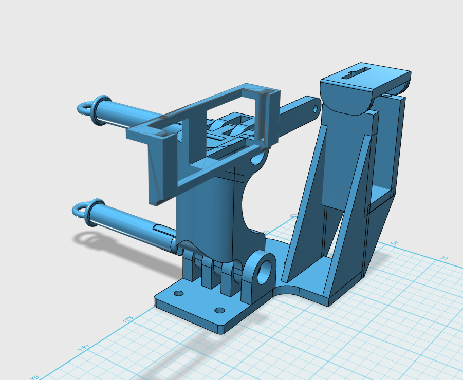
The hinge is constructed by 3d printing it.. This has to be able to come apart easy so the swingarm is detacheable from the stand and can be easily stored in a box.
The download links for printing the hinge can be found at the bottom of this block.

The way things are set up, the maximum swing at the top is just about the same as the length of the arm!

For each target, as i made them, the parts list is:

How the hinge fits together can be seen on the pictures:
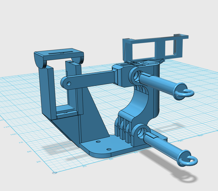


Remarks on this design:
When putthing things together, make sure you lock the outer nut on the servo arm with loctite so it won't come off, and press the cap above the servo holder on it so it fixes the servo in place with the tabs in the slots top and bottom.
The servo is put in upright with the axle at the top.
To prevent any reflection coming back to the shooter, everything is painted in flat black.

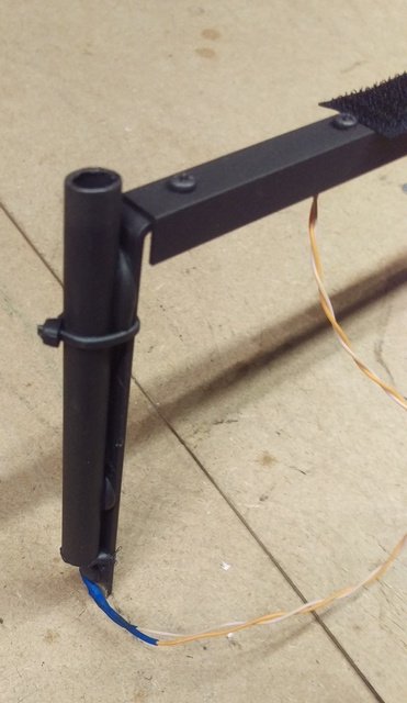
To finish things off, it's fun to put something over the targets/ldr tube. For this some cardboard with a funny face, bullseye or something else on it is painted.
A hole is made for the ldr tube and then it's attached to the arm.
Whatever you do, make sure it's not adding too much weight to the top of the arm.
The finished target assembly:

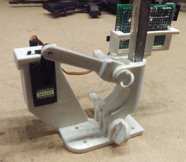

Yes, the target is balanced so that if it stands upright, it can stand on its own! Ofcourse not when it goes to either side, that is where the holes come in, they can be used to fasten this hinge to a stand.

I didn't do any after-printing finishing at all, it should just fit together and work, with two exceptions: the pin and the pinlock.

The pinlock fits kinda snug, so it's nice if you sand the sides down a bit. After fitting it to the pin, it should not be that loose so it rotates on its own, but you shouldn't need pliers to rotate it.

Also, after installing the pinlock, use some sandpaper to sand the entire pin. The pin fits tight and is intended to be sanded down.
Sand it down just enough so it will fit snug but it isn't hard to place or remove. This will also make the pinlock flush to the pin.

The picture doesn't show a stand because i don't have one. I made a crude one out of some wood, lifting the target about 25cm off the floor, setting the target at about 1.25m high.
Once i made a (foldable!!!) stand, i will add it to this page.

All the files for printing the hinge parts: