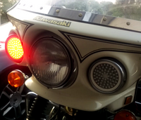
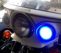
This project is for the flashers in a so-called 'chips' motorcycle (for the people that know the tv series). It is a kawasaki Z1000P, a special USA police model.
These models usually have the blue/red flashers next to the main headlight in the fairing, but once sold privately, they are taken out and replaced by either white or amber lights.
Even worse: in this country you get a ticket if you get caught even showing any red or blue lights, let alone have them working.
As it turns out, the measurements of the lights are the same as PAR36 lights (from stages etc.). Knowing that, it is possible to use some simple electronics to replace those lights with something that will work but does not get you a ticket!
Please note: this project is still active! What's here work, but things might be changed a bit or extended/expanded!
The main idea is: make lights that are a drop-in replacement but when off will not show any blue/red. Even more: they should be switcheable between 'normal' mode and 'police' mode.
Normal mode means: white or amber light, police mode is ofcourse flashing red and blue!
Knowing arduino and what it can do, in short i designed a light that will replace the old lights with some electronics and programmable LED's.
The easiest ones to use are so-called neopixels. These can be obtained online in prefabricated circular PCB's, which is perfect for this purpose!
They are not as bright as the 'official' flashers, but the light coming from them is considerable, especially if you stick 60 of them in one housing..
To have it as a 'finished product', it all has to fit in a nice housing controlled by the switches and wiring that is already there so no changes are made to anything on the motorcycle at all.
All the electronic parts needed for one replacement light:
| count | Part | example (url) |
|---|
| 4 (*) | neopixel rings, in the url all but the middle one | NEOPIXEL rings |
| 1 (*) | 12 to 5 volt converter, capable of handling the power needed on full white | 12 to 5V step down power supply |
| 1 (*) | 3 pin plug, male and female | 3 pin plug, male + female |
| 1 | arduino nano 5V | Arduino nano, 328P, 5V |
| 1 | 1 channel relay module | 1 channel relay module |
| | 5 meters wire, the usual 3 strand 220V wires will do just fine. We need at least 3 strands: 5V, GND and signal. | |
| 1 | PCB hole board | 3 X 7 cm prototype board |
| 3 | resistors , 30K |
| 1 | resistor, 1K |
| 1 | resistor, 100K |
| 3 | zener diode, 4.7V |
| 1 | L7808 power regulator |
| 1 | BC547B transistor |
| 3 | 3 pin screw terminals | 3 pin screw terminals |
| 1 | 2 pin screw teminal | |
| 1 | 3 pin header |
| 1 | 2 pin header + jumper |
| 1 | Nice to have: an ISO car plug (power + speakers, male and female parts) for a car stereo! Available at any good car parts shop. |
To have both lights replaced, you will need everything marked with (*) twice.
Screws and bolts in the project, mostly bought at microschroeven.nl. Yes, it's a bit of commercial but i tend to find everything i need there for fastening stuff!
All the measured lenghts are actual thread length.
The list of the bolts and nuts:
| Count | Item |
|---|
| 16 | M3 nut |
| 4 | M3 X 8 |
| 4 | M3 X 12 |
| 6 | M3 X 12 (iso 965!) |
| 2 | M3 X 30 (found these at the hardware store) |
Last we have some printed parts for the light and control fixture:
I printed the parts using ABS, since it can handle shocks,stresses, chemicals (salt in winter, other stuff splashed up from the road surface like diesel etc.) and higher temperatures better than PLA. I had some white for the light parts, making them blend in nicely! The control fixture can be any color that happens to be on some leftover spool, they are hidden inside the fairing.
The 'lens' can be fabricated from a piece of acrylic of 2mm thickness.
Because the LED's will be programmable RGB leds we will need something to send the signals. In this project an arduino nano is used. It's small and has enough ports for the job.
The electronics are fairly simple, but they have to be put together with care because we do have a considerable current running through some of the cables (for instance, we need 3.6A at 5V for each of the lights if they are on in max white!).
We also take care that the lights are not powered while they are not in use, so there is no chance in draining the battery of the motorcycle while it is parked or stored and the ligths are not doing anything.
The complete circuit looks like:
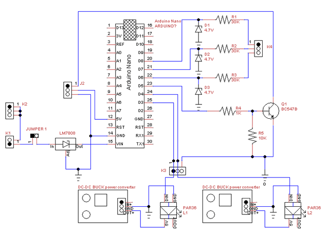
Notes on this circuit:
- The power to everything is supplied by 2 different ways:
- The arduino is powered by +12V coming from the running lights.
They switch on when the main light switch is in position 1 (running lights on, main headlight still off).
The powerdrop is done by using a 7808 and the onboard 5V regulator so neither get really hot.
The jumper to the 7808 is added so we can program the arduino 'in place' using the USB plug to power the arduino and the relay while doing that.
- The dc-dc converters get their power from the relay unit (not shown in the circuit). This gets the high-power from the 12V accessoires line, which has it's own dedicated 10A fuse.
Both in+ connections of the dc converters get connected to the NO connection of the relay
The relay unit itself gets 5V, GND and a on/off signal through the 3 pin header J2
Ground is connected to one of the black/yellow line connections that is free.
- We'll be creating the arduino circuit on the experimental board, connecting the arduino and power units using screw terminals.
- The idea behind terminal K2 is that we can simply connect 1 ground cable to the motorcycle and connect all the rest through the circuitboard.
- The standard arduino relay unit is active LOW. We don't want this because there is a chance that the relay will be activated while the arduino is not powered or starting up. So it is inverted using a BC547B and this signal is then sent to the relay through J2
- The DC-DC converters have screw terminals on them, so does the high-power side of the relay module.
- The inputs are expected to be +12V active. The resistor and zener are used as a cheap/easy level converter to 4.7V (resistor pulling 1.64mW and the zener 1.17mW, staying well below safe limits). You could use 5.1V zeners, but i like to stay below 5V.
- The inputs look like they are floating (R1, R2 and R3), but the ports will be pulled low by the zener diodes.
The pinout of the terminals and jumpers are:
- Jumper 1 - used for programming the arduino in place. Make sure this is disconnected when the arduino is plugged in on a USB cable! Normally, this is closed, providing the arduino power.
- J2 is the connection for the relay unit
- 1 - GND
- 2 - 5V
- 3 - on/off signal
- K1
- 1 - GND from motorcycle
- 2 - +12V running lights (ignition on, main light switch in position 1 or 2)
- K2 - All terminals are used for providing a GND connection to other units (relay, DC-DC converters, LED lights)
- K3
- 1 - Data pin for light 1
- 2 - Data pin for light 2
- 3 - GND like K2
- K4
- 1 - Signal input 1 (spare for future use)
- 2 - Headlight signal/switch
- 3 - Pursuit switch signal/switch
If we keep things nice and tidy, it is possible to get everything mounted on the small PCB. An example for this:
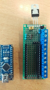
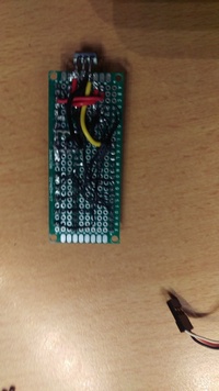
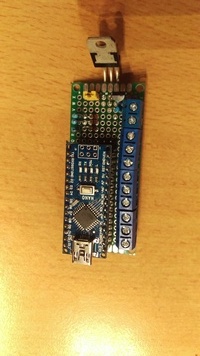
The pinout of everything on the board (terminal counting from right top to right bottom):
| Number | Connection |
|---|
| 1 | +12V |
| 2 | GND |
| 3-6 | GND connections to other circuits/modules |
| 7 | data 1 (= arduino data pin 3) |
| 8 | data 2 (= arduino data pin 4) |
| 9 | switch in 1 (= arduino data pin 6) |
| 10 | switch in 2 (= arduino data pin 7) |
| 11 | switch in 3 (= arduino data pin 8) |
The 3 pin header right against the arduino is positioned with GND (pin 3 of J2 in the circuit drawing) closest to the screw terminals, then the pins are:
| Number | Connection |
|---|
| 1 | on/off signal for relay unit |
| 2 | +5V (from arduino) |
| 3 | GND |
The position of the arduino is such that it should be possible to plug in a USB cable without having to disassemble anything.
Once finished, we have the following parts to fit together:
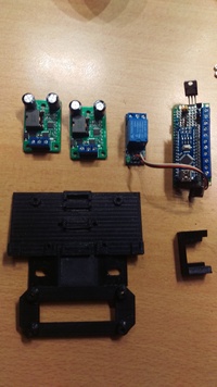
All fitted (and wired):
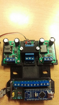
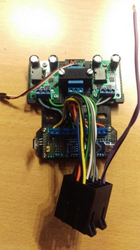
To fasten this entire 'unit' in the fairing, choose either left or right pursuit light. Take the cover and the bag on that side out of the fairing and you should be able to access the nuts on the back of the light fixture.
Take the 2 bolts off the bolts and take the washers off also. Then put the unit on the bolts (through the 'slotted' holes in the middle part of the plate), put the washers back on and then put the nuts on, tightening them not too much to break things.
The wiring is hooked up to the motorcycle harness using the car radio plug. I kept the use of the plugs as intended mostly.. the power side is actually used as power, the speaker side is used for connecting the lights.
I assigned the colored cables as this:
(the terminal connections on the arduino board are counted from left to right, starting with 1)
Power connector (using standard color coding)
| Cable color | Used for | terminal | Attached to |
|---|
| black | GND | 2 | black/yellow, there is a 2-way plug empty in the fairing for this |
| yellow | running lights | 1 | Splice into the BLUE wire of the left blinker, it can be done without damaging the cable. This way, nothing will work until you put the light switch to the 'PO' or 'ON' position (or: whenever the running lights switch on. I am unsure if all bikes have this PO position..). |
| red | +12v accessoiry feed | comm on relay unit | Directly attached to the 2-way white/blue wire in the fairing |
| orange | pursuit switch | 9 | Directly connected to the green/yellow wire in the fairing using a flat connector |
| blue | main light (low beam) | 10 | take out he main headlight and splice it in the low beam wire. |
Speaker connector (using standard color coding)
| Cable color | Used for | terminal |
|---|
| green | 5V light #1 | OUT+ (right most terminal) on left DC converter |
| green/black | GND light #1 | 5 |
| grey | 5V light #2 | OUT+ (right most terminal) on right DC converter |
| grey/black | GND light #2 | 6 |
| white | data light #1 | 7 |
| white/black | data light #2 | 8 |
| violet | free for future use |
| violet/black | free for future use |
Connections between arduino and modules
| starting | Used for | ending |
|---|
| 3 | GND | GND (middle terminal) left DC converter |
| 4 | GND | GND (middle terminal) right DC converter |
| NO terminal of the relay unit | +12V | IN+ (left most terminal) on left and right DC converter |
For the connection to the lights i used some 3 wire fire resistant and flame retardant cables, making sure to note down what color is for what. On one end they get connected to the speaker car plug.
The other end is fed through the hole in the fairing for the lights and then the female part of the plugs are attached to them (making sure the pinout matches the plug on the light!).
With everything in position behind the left flasher it looks like this:
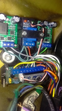
For the lights the best thing to do is start with actually damaging the rings! Or at least, the insulation on them.
The reason for this is that the outer cirle won't have to (and probably can't) handle all the power going through it, each circle of leds will be powered individually from the main powerline.
Lay them facedown on a table like they would be sitting in the body. Then locate the contacts on the PCB and draw a line from there all the way to the top with a marker.
Flip everything around (so leds up) and copy that line.
Now carefully scratch off the insulation of the PCB.
Starting on the backside, make sure the pcb contacts are facing you and only remove the insulation from the middle UP.
Then flip the circle over, making sure that the contacts again face you, and remove the insulation from the middle DOWN.
Also, when working on the LED side, take care not to remove insulation from the data lead!
Once done, take a piece of wire of about 25 cm and remove 3,5cm of the insulation. Place the rings as they sit in the body (i.e. inside eachother with the correct distance all around) and alighn the removed insulation places.
Now solder the MINUS lead on the LED side leaving the rest of the cable point out.
Then flip over the entire assembly and solder the PLUS lead to the backside, again having the rest of the cable pointing out.
You end up with the LED circles fixed, with a wire sticking out on 2 opposite sides.
I forgot to take pictures of this, but i did take pictures assembled:
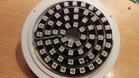
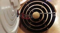
Last thing to do is to solder the data wires. On the PCB there are 2 pads for this, a data in and a data out.
Start with soldering a piece of wire of about 25cm to the 'data in' of the largest circle. Then solder a short wire from the 'data out' on the same circle to the 'data in' of the next ring (i.e. daisy-chain the circles).
Next repeat this for the other rings until you end up on the inner circle.
(in the pictures, these are the short red wires on the backside of the rings).
Testing
Testing the assembly can be done using an arduino and a little testing program.
Take a USB adapter for charging your phone and an old USB plug you won't be using anymore. Cut off the end of the USB plug that usually plugs into the phone and strip the cable carefully about 10 cm.
You should see 4 small cables. All but the red and black can be cut away.
Last, take some loose wire, 2 pieces of around 10cm length. They do not have to be the same color.
Make sure there is no power on the USB adapter or the arduino!
Attach the single red wire of the USB cable to the 5V cable of the light to be tested.
Next, twist 2 wires to the black wire of the USB plug and attach these to the GND of the light and the GND pin of the arduino.
Last, connect the data wire of the light you are testing to either pin 3 or pin 4 of the arduino.
While testing the arduino is powered by the USB plug, so we do not have to attach a 5V lead to it.
Before you test things, a small test program has to be loaded in the arduino.
Download the test program and upload it to the arduino using the GUI (available at arduino download page) and Fastled library from: fastled project page
Once it is uploaded you should see the light flashing either red or blue, depending on what pin you attached the data line to. You can verify the other color by unplugging the power, then changing the pin and then plugging in the power again.
If you see something not working, check all the connections, soldering on the leds, etc..
The 3D printed housing parts should fit together snug and there shouldn't be any warping. If there is, they won't sit flush.
The round ridges in the backplate are where the neopixel rings sit on.
There is no need to fasten the led rings to the ridges because with the correct size of the filling ring these get sandwidched between these ridges and the lens.
Also, by the way the rings are soldered, they are kept in position by the wires and connections.
Here is where those special iso 965 bolts come in. In this example, 3 holes are drilled in the outer ring. Then, a special drillbit is used to sink the heads of the bolts in the ring so their tops are flush with the top of the ring!
After this is done, it is best to use a grinder to take 1 mm off of the threads so they do not stick out of the nut (which is around 2mm high).
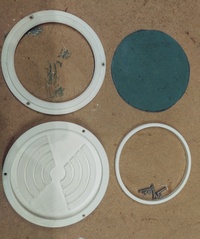
The last thing needed are holes for the cables of the LED assembly
Position the assembly on the main body and mark 3 holes just outside the outer ring on the data wire side (or: where the soldering pads are on the led rings).
There is enough room for the plus wire to run around the outermost circle to the same place, so the holes can all be next to eachother in the order: plus, minus, data
After all this, sand and paint all the white parts with white paint. It might sound strange, but 3d prints with abs have tiny holes where water can work its way in. So when the weather starts getting wetter and colder (freezing) this might cause cracks.
Another reason is that the surface of a 3d printed project is rough. With a nice high gloss paint it is as smooth as the fairing itself, making it even more look like it always belonged there.
Final assembly is done by first threading the wires through the holes drilled for them in the main body.
When pulling the wires through, the LED assembly will fall into place and the plus wire can be positioned.
The endresult will look something like this:

The light has to be weatherproof, so it is smart to use some sort of gasket.
I had some bathroom silicon sealant laying around, which is white and stays flexible when dry. Perfect for the purpose!
Apply a thin layer on the topring outer ring and some where the acrylic sits. It will seal things just fine. Then assemble all the parts so it becomes 1 unit.
Last thing to do is to attach the (male!) part of the 3 pin plug to the wires, and glue that to the back of the body with some epoxy glue, and the whole unit is finished.
The endresult will look something like in the pictures below:
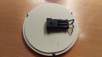
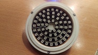
In the above picture, the blue wire is the data wire, the middle is GND and the bottom one is +5V.
Placing the light in the fairing is done just like replacing the normal lights. It fits snug so there is no rattling!

Last, but not least, we need software to make everything work!!
For this, download my code here: Flash.ino
Download it, and put it in a folder called flash.
If you don't have it already, install the arduino GUI from: https://www.arduino.cc/en/main/software
Last, you will need the Fastled library installed from: fastled project page
Once installed, you can open the arduino gui, load the flash.ino file, connect the arduino itself and upload the program.
Please read the remarks in the flash.ini file for any specifics and how things are supposed to work with the current version of flash.ino!
Once programmed and everything plugged in, we now should have working flashers! The current programmed flash sequence is 3 short flashes, then switch to the other side.
